Coding & Modulation
Modulation
Adaptive Coding and Modulation (ACM)
ACM – Adaptive Coding & Modulation, Up to 1dB/Sec / PtMP configuration
Adaptive Coding and Modulation (ACM) is a feature incorporated into the DVB-S2 satellite specification, allowing real-time adaptation of transmission parameters according to the link conditions. Although ACM was originally designed for optimizing unicast services, this article discusses the expansion of its usage to broadcasting streams as well. ACM extends VCM by providing a feedback path from the receiver to the transmitter to allow the level of error protection to be varied dynamically in accordance with varying propagation conditions. Claims of performance improvements exceeding 100% have been made for ACM in terms of satellite capacity gain.
ACM is not a new concept. It has been used for some time in wireless communications, including terrestrial microwave applications, and more recently over satellite links. Its primary function is to optimize throughput in a wireless data link, by adapting the modulation order used and the Forward Error Correction code rate (which both directly affect spectral efficiency, expressed in bits per second per Hertz), according to the noise conditions (or other impairments) on the link.
Implicit in this concept is that the symbol rate (and power) of the wireless communication system must remain constant. This ensures that the bandwidth allocated for a particular link is never exceeded. Given that the symbol rate does not change, if modulation and coding are changed, the data rate must therefore be modified.
OptiACMVideoACM
Advanced ACM
Variable Coding and Modulation (VCM)
Variable Coded Modulation (VCM) methods allow users to change coding and modulation during a communication session to adapt the transmitted information data rate to dynamic link conditions. Compared to traditional communication systems that use constant coding and modulation designed for worst-case link conditions, VCMcan significantly increase overall effective data throughput when the radio is configured adaptively to fully utilize link capacity.
VCM can be used to provide different levels of error protection to different components within the service. It does this by allowing different combinations of modulation and FEC rate to be applied to different parts of the data stream.
APSK
8APSK, 16APSK, 32APSK, 64APSK, 128APSK, 256APSK
Amplitude and phase-shift keying or asymmetric phase-shift keying (APSK) is a digital modulation scheme that conveys data by changing, or modulating, both the amplitude and the phase of a reference signal (the carrier wave). In other words, it combines both amplitude-shift keying (ASK) and phase-shift keying (PSK) to increase the symbol-set. It can be considered as a superclass of quadrature amplitude modulation (QAM). The advantage over conventional QAM, for example 16-QAM, is lower number of possible amplitude levels. Moreover, a careful design of the constellation geometry can approach the Gaussian capacity as the constellation size grows to infinity. For the regular QAM constellations, a gap of 1.56 dB is observed. The previous solution, where the constellation has a Gaussian shape, is called constellation shaping.
PSK Modulation
Phase-shift keying is a digital modulation process which conveys data by changing the phase of a constant frequency reference signal. The modulation is accomplished by varying the sine and cosine inputs at a precise time. It is widely used for wireless LANs, RFID and Bluetooth communication.
BPSK
Binary Phase Shift Keying (BPSK) is a two phase modulation scheme, where the 0’s and 1’s in a binary message are represented by two different phase states in the carrier signal: θ=0∘\theta=0^{\circ} for binary 1 and θ=180∘\theta=180^{\circ} for binary 0. In digital modulation techniques, a set of basis functions are chosen for a particular modulation scheme. Generally, the basis functions are orthogonal to each other. Basis functions can be derived using Gram Schmidt orthogonalization procedure [1]. Once the basis functions are chosen, any vector in the signal space can be represented as a linear combination of them. In BPSK, only one sinusoid is taken as the basis function. Modulation is achieved by varying the phase of the sinusoid depending on the message bits.
QPSK
This technique is also known as quaternary PSK, quadriphase PSK or 4-PSK. QPSK refers to a type of phase modulation technique where there are four states involved. It uses four points on the constellation diagram, equispaced around a circle. Since QPSK has four phases, it can encode two bits per symbol, thereby increasing the data rate.
8-PSK
8PSK (8 Phase Shift Keying) is a phase modulation algorithm. Phase modulation is a version of frequency modulation where the phase of the carrier wave is modulated to encode bits of digital information in each phase change. The “PSK” in 8PSK refers to the use of Phased Shift Keying. Phased Shift Keying is a form of phase modulation which is accomplished by the use of a discrete number of states. 8PSK refers to PSK with 8 sates. With half that number of states, you will have QPSK. With twice the number of states as 8PSK, you will have 16PSK. Because QPSK has 8 possible states 8PSK is able to encode three bits per symbol. 8PSK is less tolerant of link degradation than QPSK, but provides more data capacity.
Offset QPSK / OQPSK
The OQPSK modulation is a PSK modulation, using 2 bits per symbol and a delay of one bit in the in quadrature signal
QAM
Quadrature amplitude modulation (QAM) is the name of a family of digital modulation methods and a related family of analog modulation methods widely used in modern telecommunications to transmit information. It conveys two analog message signals, or two digital bit streams, by changing (modulating) the amplitudes of two carrier waves, using the amplitude-shift keying (ASK) digital modulation scheme or amplitude modulation (AM) analog modulation scheme. The two carrier waves of the same frequency, usually sinusoids, are out of phase with each other by 90° and are thus called quadrature carriers or quadrature components — hence the name of the scheme. The modulated waves are summed, and the final waveform is a combination of both phase-shift keying (PSK) and amplitude-shift keying (ASK), or, in the analog case, of phase modulation (PM) and amplitude modulation. In the digital QAM case, multiple discrete values of phase and multiple discrete values of amplitude are used. Phase shift keying (PSK) is a simpler form of QAM in which the amplitude of the carrier is constant and only the phase is shifted. QAM is used extensively as a modulation scheme for digital telecommunication systems, such as in 802.11 Wi-Fi standards. Arbitrarily high spectral efficiencies can be achieved with QAM by setting a suitable constellation size, limited only by the noise level and linearity of the communications channel.
Coding (Encoder / Decoder)
Differential Encoding
Encoding in which signal significant conditions represent binary data, such as "0" and "1", and are represented as changes to succeeding values rather than with respect to a given reference. Note: An example of differential encoding is phase-shift keying (PSK) in which the information is not conveyed by the absolute phase of the signal with respect to a reference, but by the difference between phases of successive symbols, thus eliminating the requirement for a phase reference at the receiver.
Forward Error Correction (FEC)
BCH (Bose-Chaudhuri-Hocquenghem) Coding / BCH Decoder
In coding theory, the BCH codes or Bose–Chaudhuri–Hocquenghem codes form a class of cyclic error-correcting codes that are constructed using polynomials over a finite field (also called Galois field). BCH codes were invented in 1959 by French mathematician Alexis Hocquenghem, and independently in 1960 by Raj Bose and D. K. Ray-Chaudhuri. The name Bose–Chaudhuri–Hocquenghem (and the acronym BCH) arises from the initials of the inventors' surnames (mistakenly, in the case of Ray-Chaudhuri).
One of the key features of BCH codes is that during code design, there is a precise control over the number of symbol errors correctable by the code. In particular, it is possible to design binary BCH codes that can correct multiple bit errors. Another advantage of BCH codes is the ease with which they can be decoded, namely, via an algebraic method known as syndrome decoding. This simplifies the design of the decoder for these codes, using small low-power electronic hardware.
BCH codes are used in applications such as satellite communications, compact disc players, DVDs, disk drives, solid-state drives and two-dimensional bar codes.
LDPC (Low Density Parity Check) / LDPC Decoder
LDPC decoding is usually an iterative process, where the decoder converges after a number of iterations, providing quasi-error free data. The maximum allowed number of iterations defines the time spent in the LDPC decoder but also the »implementation loss« between actual decoder performance and the theoretical decoding threshold. There are various implementation options for LDPC decoders, including use of »early termination« strategies and internal parallelism to speed up the decoding process and improve throughput. Although DVB-S2X defines a number of additional coding and modulation schemes (MODCODs), LDPC decoders in DVB-S2 and DVB-S2X are largely identical. Depending on target technology, the LDPC decoder may limit the MODEM throughput; support for carrier sizes significantly above 100 MSps typically requires a combination of pipelining and multi-instance design. Due to the iterative nature in processing data, LDPC decoder implementation performance benefits from the availability of high-speed, multi-port RAM.
Reed Solomon
Reed–Solomon codes operate on a block of data treated as a set of finite field elements called symbols. For example, a block of 4096 bytes (32768 bits) could be treated as a set of 2731 12 bit symbols, where each symbol is a finite field element of GF(212), the last symbol padded with four 0 bits. Reed–Solomon codes are able to detect and correct multiple symbol errors. By adding t check symbols to the data, a Reed–Solomon code can detect any combination of up to and including t erroneous symbols, or correct up to and including ⌊t/2⌋ symbols. As an erasure code, it can correct up to and including t known erasures, or it can detect and correct combinations of errors and erasures. Reed–Solomon codes are also suitable as multiple-burst bit-error correcting codes, since a sequence of b + 1 consecutive bit errors can affect at most two symbols of size b. The choice of t is up to the designer of the code, and may be selected within wide limits. There are two basic types of Reed–Solomon codes, original view and BCH view, with BCH view being the most common as BCH view decoders are faster and require less working storage than original view decoders.
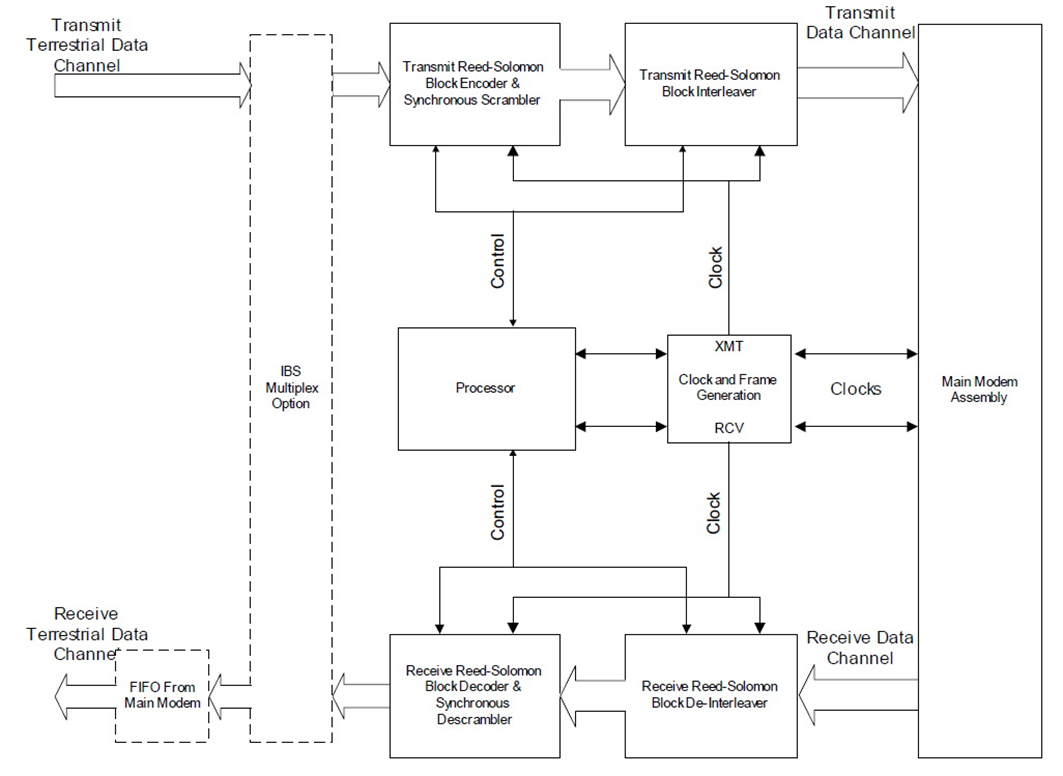
Reed-Solomon Codec Simplified Block Diagram
Trellis Code Modulation / Trellis Coding (FAST Option)
Trellis modulation (also known as trellis coded modulation, or simply TCM) is a modulation scheme that transmits information with high efficiency over band-limited channels such as telephone lines. Gottfried Ungerboeck invented trellis modulation while working for IBM in the 1970s, and first described it in a conference paper in 1976. It went largely unnoticed, however, until he published a new, detailed exposition in 1982 that achieved sudden and widespread recognition.
In the late 1980s, modems operating over plain old telephone service (POTS) typically achieved 9.6 kbit/s by employing four bits per symbol QAM modulation at 2,400 baud (symbols/second). This bit rate ceiling existed despite the best efforts of many researchers, and some engineers predicted that without a major upgrade of the public phone infrastructure, the maximum achievable rate for a POTS modem might be 14 kbit/s for two-way communication (3,429 baud × 4 bits/symbol, using QAM).
14 kbit/s is only 40% of the theoretical maximum bit rate predicted by Shannon's theorem for POTS lines (approximately 35 kbit/s).[1] Ungerboeck's theories demonstrated that there was considerable untapped potential in the system, and by applying the concept to new modem standards, speed rapidly increased to 14.4, 28.8 and ultimately 33.6 kbit/s.
The name trellis derives from the fact that a state diagram of the technique closely resembles a trellis lattice. The scheme is basically a convolutional code of rates (r, r+1). Ungerboeck's unique contribution is to apply the parity check for each symbol, instead of the older technique of applying it to the bit stream then modulating the bitsHe called the key idea mapping by set partitions. This idea groups symbols in a tree-like structure, then separates them into two limbs of equal size. At each "limb" of the tree, the symbols are further apart.
Turbo Code / Turbo Product Codec (Hardware Option)
Turbo coding is an FEC technique developed within the last few years, which delivers significant performance improvements compared to more traditional techniques. Two general classes of Turbo Codes have been developed, Turbo Convolutional Codes (TCC), and Turbo Product Codes (TPC, a block coding technique). A Turbo Product Code is a 2 or 3 dimensional array of block codes. Encoding is relatively straightforward, but decoding is a very complex process requiring multiple iterations of processing for maximum performance to be achieved.
Unlike the popular method of concatenating a R-S codec with a primary FEC codec, Turbo Product Coding is an entirely stand-alone method. It does not require the complex interleaving/de-interleaving of the R-S approach, and consequently, decoding delays are significantly reduced. Furthermore, the traditional concatenated R-S schemes exhibit a very pronounced threshold effect – a small reduction in Eb/No can result in total loss of demod and decoder synchronization. TPC does not suffer from this problem – the demod and decoder remain synchronized down to the point where the output error rate becomes unusable. This is considered to be a particularly advantageous characteristic in a fading environment. Typically, in QPSK, 8-PSK and 16-QAM TPC modes the demod and decoder can remain synchronized 2 – 3 dB below the Viterbi/Reed-Solomon or TCM cases.
eTPC Turbo code - Enhanced Turbo Product Code
The eTPC codes are a parity code applied along a diagonal traverse through the TPC block (also referred to as “hyper diagonal parity”). This coding is applied on top of the TPC coding to give an added degree of error correction power. During eTPC encoding a parity bit is computed for each diagonal through the TPC encoded block and included as an additional parity row (in the case of 2D eTPCS) or an additional parity plane for 3D eTPCs in the encoded block. This is shown for a 2D eTPC block below. The code rate of the example eTPC is now 3/16.
The addition of the enhanced TPC coding to the TPC block slightly reduces the code rate of the block code. However, it offers another degree of coding flexibility in creating a block code targeted at a specific data size and code rate.
The additional coding dimension offered by the eTPC diagonal parity improves the weight enumeration of the minimum weight codewords. The diagonal axis effectively lowers the number of Hamming distance (dmin) codewords. The benefit of using the eTPCs can be observed graphically on the BER vs. Eb/No plot. When eTPCs are added to a TPC block the slope of the asymptotic bound for eTPCs is steeper than the non-eTPC block. The location of the asymptotic bound is also lower (at a smaller BER value) for the eTPC code. One case where the use of eTPC technology is often used is when a very high rate code is desired (e.g. above rate .90). An example of this is shown in Figure 3. In this example 2 codes are shown for a block size of 2k bits. The first code is a conventional TPC code of (64,57)x(32,31) for a code rate of .95. The BER performance of this code is plotted for 8 decoder iterations in an AWGN channel with BPSK modulation. Also plotted is the performance of an eTPC (64,57)x(32,30)+ code with 8 iterations and a code rate of .92. As can be seen on the plot, the performance of the eTPC is considerably better (over 1 dB) than the conventional TPC even though the code rate is only slightly less. Another condition where the use of eTPC coding offers performance advantages is when very small BER values are required in the system. This is typically at BER values smaller than 10-7. An example is shown in Figure 4 for a (32,26)x(32,26) TPC and eTPC code. The code rate of the TPC code is .66 while the code rate of the eTPC code is .63. The BER performance of the conventional TPC approaches an asymptotic bound at a BER of approximately 10-6 and then a slight flare is encountered. The eTPC code does not encounter any flaring until much smaller BER values and as a result its performance is considerably better than the conventional TPC for these small BER values. The eTPC code performance would encounter a region of flaring approximately four decades lower. For the system requiring small BER values, eTPCs can significantly improve the overall BER performance.
Viterbi FEC
It is optimal algorithm for decoding of Convolutional code. It is dominant technique for Convolutional codes. It has advantages like satisfactory bit error performance, low cost, fixed decoding time. The viterbi algorithm proposed in 1967 is the most extensively decoding algorithm for Convolutional codes. It is powerful method for forward error correction. It has been widely deployed in much wireless communication system like IEEE 802.11a/g, Wi-Max, WCDMA and GSM to improve capacity of communication channel. The consumer demands for sophisticated portable wireless communication devices are high. So need for high speed viterbi decoder increasing.